A clear visual can make a complex dental plan feel simple. This guide explains how to read a dental implant diagram so you can see what your dentist sees, understand the steps, and ask better questions at your appointment. A good diagram shows parts of the implant, nearby anatomy, and planned restorations so you know the “why” behind the treatment and what to expect during and after care.
What Is Shown in a Dental Implant Diagram
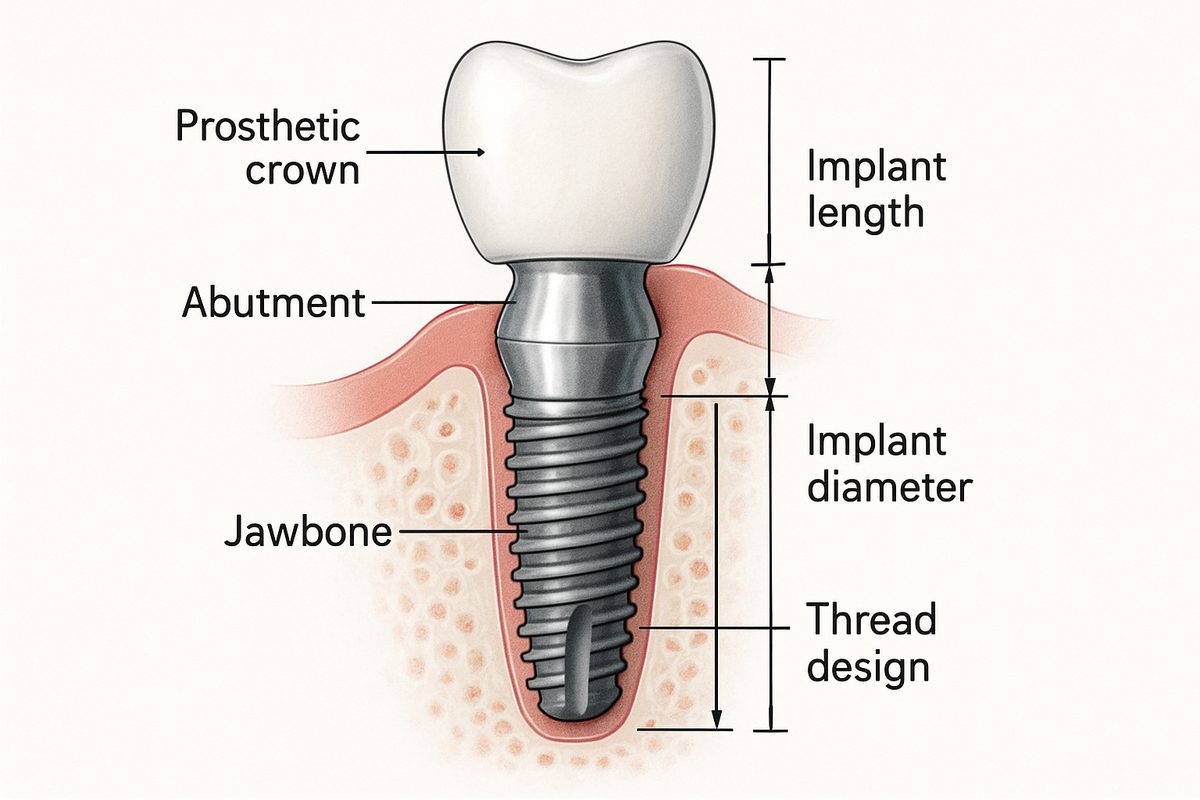
Diagrams typically show the implant fixture (the part that acts like a tooth root), the abutment (the connector), and the prosthetic crown or denture. You’ll also see the surrounding jawbone and gum tissue. Diagrams may label nearby structures like nerves or the sinus cavity. Together these elements help explain how the implant sits in the mouth and how it supports the visible tooth replacement.
Key Parts of a Dental Implant Diagram
Look for labels on implant length and diameter, which show how deep and wide the implant goes into bone. Thread design and implant shape are often pictured to explain stability. Abutment shape and crown contours show how the final tooth will attach and look. Important landmarks—such as the inferior alveolar nerve in the lower jaw or the maxillary sinus in the upper—are usually marked to show safe distances for placement.
How to Read a Dental Implant Diagram
Diagrams come in different views: cross-section slices show bone and implant depth, lateral views show side profiles, occlusal views show top-down spacing, and 3D views show overall position. Pay attention to measurement lines and numbers that indicate millimeters of bone or clearance from nerves. Color coding often differentiates bone, soft tissue, metal, and prosthetic parts. Check the scale and orientation so you know which side of the mouth you’re looking at.
Types of Dental Implant Diagrams and Images
Cross-sectional diagrams
Cross-sections slice through the jaw to show the bone-to-implant relationship and where the gum line meets the implant. These are useful for seeing whether bone height is adequate and where grafts might be needed. They make it easier to visualize how deep the implant sits relative to neighboring roots.
3D/CBCT renderings
CBCT (cone beam CT) creates 3D, volumetric images. These renderings let clinicians view bone volume from any angle, measure distances to nerves or sinuses, and plan exact implant positions. 3D views also support guided surgery by converting scans into surgical guides or digital plans.
Surgical guide and prosthetic diagrams
Surgical guide diagrams show the template used during placement, including guide sleeves and drill paths. Prosthetic maps indicate where crowns, abutments, and attachments will sit. These images connect the surgical plan to the final restoration and help ensure components line up precisely.
Common Procedures Illustrated by Dental Implant Diagrams
Single-tooth replacement diagrams focus on one implant and crown, highlighting spacing and adjacent roots. Implant-supported bridge diagrams show two or more implants supporting multiple connected crowns. Full-arch or All-on-4 diagrams display strategic implant angles and prosthetic bars for replacing an entire arch. Diagrams for bone grafts or sinus lifts show added material and how it changes bone height for safe implant placement.
What Markers on a Dental Implant Diagram Affect Your Treatment
Bone density and volume markers determine whether an implant will be stable or if grafting is needed. Proximity to the nerve or sinus affects implant length and angulation—if too close, staged surgery or special techniques may be required. Angulation and spacing relative to nearby teeth influence which abutment and crown type are chosen. All these markers guide the clinician’s choice of implant system and the need for additional procedures.
Questions to Ask Your Dentist When Reviewing Your Dental Implant Diagram
Ask why a specific implant size and position were chosen and how it affects long-term success. Ask if bone grafting or a sinus lift is needed, and what that means for healing time. Ask about risks related to nearby nerves or sinuses and how they will be avoided. Also ask what material will be used for the final restoration and how many appointments the process will take.
How Dental Associates of Colorado Uses Dental Implant Diagrams in Care Planning
At Dental Associates of Colorado, diagrams and 3D scans are part of team planning led by prosthodontist Dr. Seung H. Lee and oral & maxillofacial surgeon Dr. Jonathan Jundt. CBCT and intraoral scans create accurate 3D models for guided surgery and prosthetic design. The practice’s in-house lab and experienced technicians help translate diagrams into restorations that fit and look natural. This coordinated approach reduces surprises and improves predictable outcomes.
What to Expect at an Appointment When You Review Your Dental Implant Diagram
Expect imaging (panoramic X-ray or CBCT) and a digital intraoral scan to be taken first. The clinician will walk through the diagram, point out bone measurements and nearby anatomy, and explain the proposed implant size and position. You’ll review a timeline for surgery and restoration, discuss sedation options if needed, and hear about financing. If available, the in-house lab or model may be shown to verify fit and shade.
Conclusion — Using a Dental Implant Diagram to Make an Informed Decision
A dental implant diagram is a practical tool to see risks, steps, and expected outcomes before treatment. It helps you compare options, understand the timeline, and ask focused questions. If you’d like a personalized review of your images and a clear plan, schedule a consult to go over your implant diagram with the team.